Rotary Base
Mechanical:


The rotary base will act both as an angular control device allowing the launcher to fire at the desired angle and a mounting device for the barrel of the launcher and the autoloading mechanism. The launcher barrel will be mounted at 45 degrees, as this is our firing angle. A large lazy Susan bearing is implemented into the design of the rotary base. The inner race of the bearing is attached to the barrel mount and is driven by the central shaft. The outer race of the bearing is mounted to the frame and is stationary.
Barrel Mount:

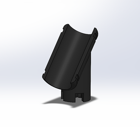
The barrel mount connects to the rotary base and is held down by the force of the air cannon and autoloader. The barrel is held by the inner curve of the mount and fastened with hose clamps.
Electrical:

AMT102-v Encoder

MD10C R3 Motor Driver

DC Motor
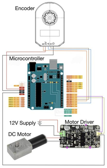
The rotary base will include the three electrical components shown above. The DC motor will be used to drive a central shaft which will rotate in order to rotate the launcher to various angles. The Motor driver will be used to drive the motor. The driver will allow us to control the movement of the motor, whether it is off, rotating clockwise, or rotating counterclockwise. Finally, the encoder will be used to read the exact angle of the central shaft.
The Encoder:
The encoder I will be using is the CUI Devices Series: AMT102-v. It is an incremental rotary encoder. It has a resolution of 2048 pulses of revolution. This means it can read down to a minimum angle of 0.178 degrees. The datasheet for this encoder is provided in the resources page.
The DC Motor:
The DC motor is a 12 volt 16 RPM motor with 70 kg.cm of torque.
Electrical Diagram:

Software:
The software will control the angle of the launcher by driving the DC motor with control through the motor driver. The encoder will provide constant feedback to the software. The software will use the feedback from the encoder to stop the motor when the shaft reaches the desired angle.
Flow Chart:


